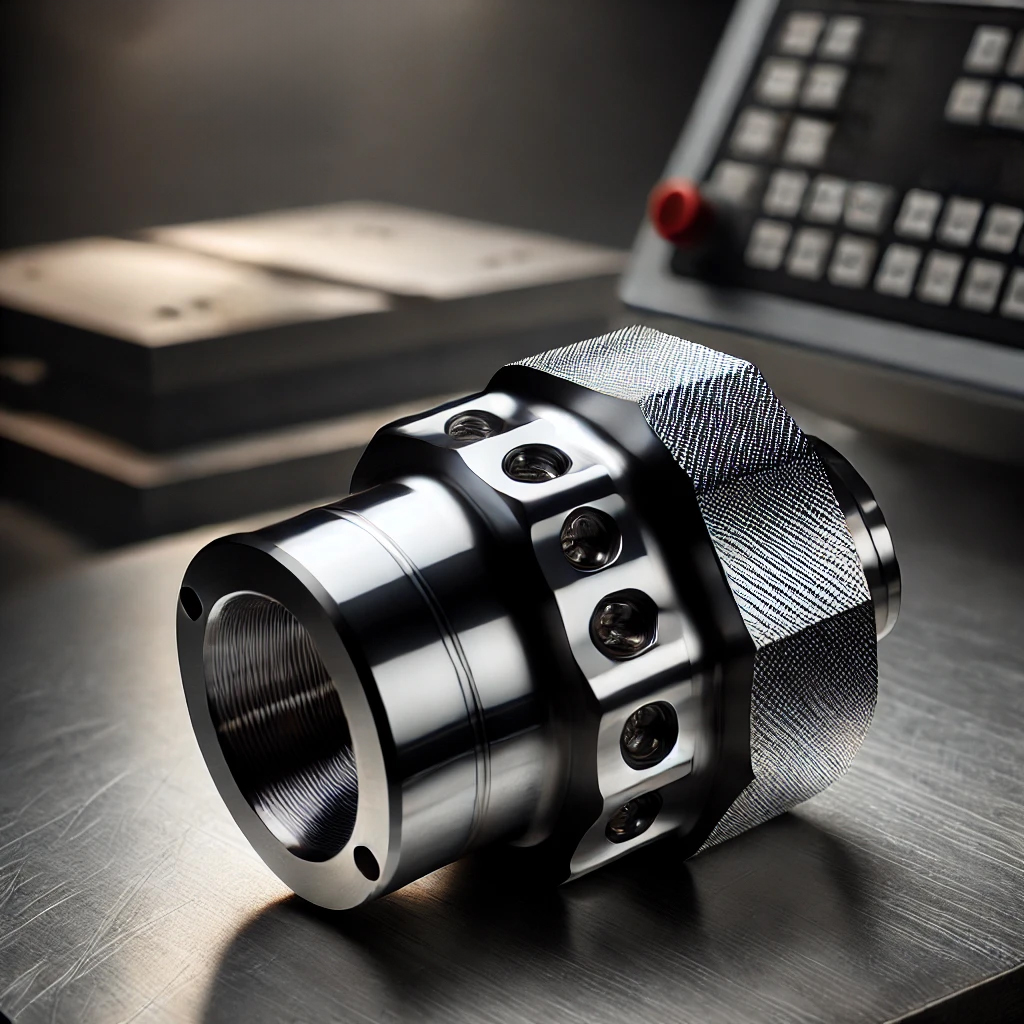
The Essential Guide to CNC Machining Tolerances
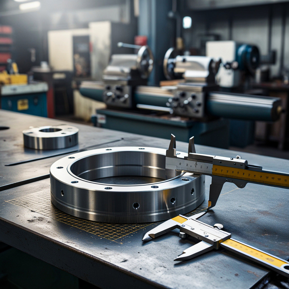
Understanding tolerances is not just a technical necessity—it’s a critical component of successful product design and manufacturing. Tolerances define the permissible limits of variation in a part’s dimensions, shape, and surface quality. They ensure that components fit together as intended, function correctly under various conditions, and maintain their integrity over time.
Why do tolerances matter so much? Because in industries where precision is paramount—like aerospace, automotive, and medical devices—even the smallest deviation can lead to significant problems. A slight misalignment could compromise the safety of an aircraft, a minor dimensional error could lead to premature wear in an engine, and an inadequate surface finish could reduce the effectiveness of a medical implant. Tolerance is what keeps these potential issues at bay, ensuring that products not only meet design specifications but also perform reliably in the field.
Key Terms in CNC Machining Tolerances:
Before diving deeper into the intricacies of CNC machining tolerances, it’s essential to understand the fundamental terms that define how these tolerances are applied. These terms are the building blocks that ensure every part is manufactured to meet precise standards.
- Basic Size: This is the theoretical size from which limits of tolerance are derived. It’s the target dimension that designers aim for, providing a starting point before any tolerances are applied.
- Actual Size: Once a part is machined, the actual size refers to the measured dimension. It’s this measurement that is compared against the limits set by the tolerances to ensure the part meets specifications.
- Limits of Size: These define the maximum and minimum permissible sizes a part can have and still be considered within tolerance. For example, if a part’s basic size is 10 mm (about 0.39 in) with a tolerance of ±0.05 mm, the limits of size would be 10.05 mm (about 0.4 in) and 9.95 mm (about 0.39 in).
- Deviation: Deviation is the difference between the actual size of the part and the basic size. It indicates how much a part’s dimension has varied from the target size, within the set limits.
- Datum: In the context of GD&T (Geometric Dimensioning and Tolerancing), a datum is a reference point, line, or surface on a part used to define the location or orientation of other features. It acts as the foundation from which measurements are taken.
- Tolerance Zone: This is the range between the upper and lower limits of a dimension where the actual size of a part must fall. For geometric tolerances, the tolerance zone is defined by a specific shape or area within which the feature must lie.
Understanding these terms is crucial for anyone working with CNC machining, as they form the foundation for ensuring that every part produced meets the required precision. With these basics covered, you’re better equipped to navigate the complexities of CNC machining tolerances.
Understanding the Basics of Tolerances
Understanding the different types of tolerances and how they apply to your designs is crucial for achieving the desired level of precision and functionality.
Dimensional Tolerances:
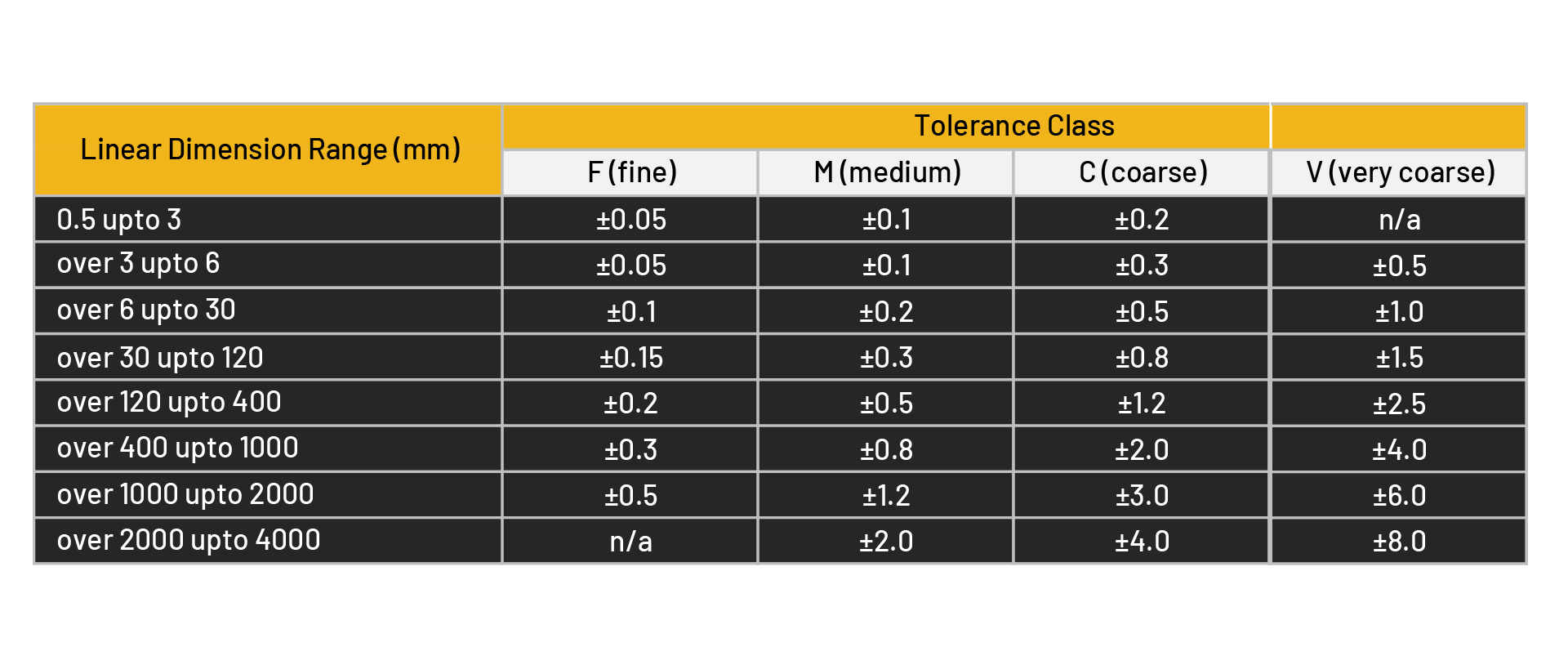
This CNC Tolerances Chart provides a clear breakdown of allowable dimensional variations based on the size of the component and the required precision level. The chart categorizes tolerances into four levels: Fine (F), Medium (M), Coarse (C), and Very Coarse (V), corresponding to different linear dimension ranges. Use this chart to quickly determine the appropriate tolerance level for your specific application, ensuring components fit and function as intended.
Dimensional tolerances are the most specified type of tolerance in CNC machining. They dictate the allowable variation in a part’s linear dimensions, such as length, width, height, or diameter. These tolerances are essential for ensuring that parts fit together correctly in an assembly.
For example, consider a shaft that needs to fit into a bearing. The shaft's diameter must be within a specific range—neither too large nor too small—to ensure a proper fit. If the diameter falls outside the specified tolerance, the shaft might not fit into the bearing, or it could lead to excessive wear and tear due to improper fitting.
The achievable dimensional tolerances can vary depending on the material being used and the machining process. For instance, softer materials like aluminum are easier to machine to tight tolerances, while harder materials like titanium may require more precise tools and careful control of machining parameters. Understanding these material-specific behaviors is key to selecting the appropriate tolerances for your design.
Unilateral and Bilateral Tolerances:
In CNC machining, not every dimension needs the same level of precision. Sometimes, a dimension can vary more in one direction than the other. This is where unilateral and bilateral tolerances come into play, offering the flexibility needed to ensure that parts meet both functional and cost-efficiency goals.
- Unilateral Tolerances allow for variation in only one direction—either above or below the nominal dimension. This is particularly useful in scenarios where excess material could cause issues, but a slight reduction wouldn’t affect performance. For instance, imagine a shaft that must fit into a hole. If the shaft is slightly smaller, it will still fit, but if it’s too large, it won’t. Unilateral tolerances ensure the part remains functional without unnecessary precision that could increase production costs.
- Bilateral Tolerances, on the other hand, permit variation in both directions—above and below the nominal dimension. This type of tolerance is often used when the exact size isn’t critical, but the part still needs to fit within a specific range. For example, in components that need to interlock or align, bilateral tolerances allow for minor adjustments during assembly without compromising the overall functionality.
The choice between unilateral and bilateral tolerances depends on the part’s function and the criticality of its fit within the assembly. Unilateral tolerances are ideal when you need strict control in one direction, while bilateral tolerances offer a balanced approach, allowing for flexibility on both sides.
Limit Tolerances:
When it comes to precision engineering, not all dimensions can afford a "close enough" approach. That’s where limit tolerances step in. These are the strict boundaries that dictate the maximum and minimum dimensions a part can have. Imagine a door that must fit perfectly into its frame—too big, and it won’t close; too small, and it leaves gaps. In CNC machining, these limits ensure every part fits just right, without compromising the entire assembly.
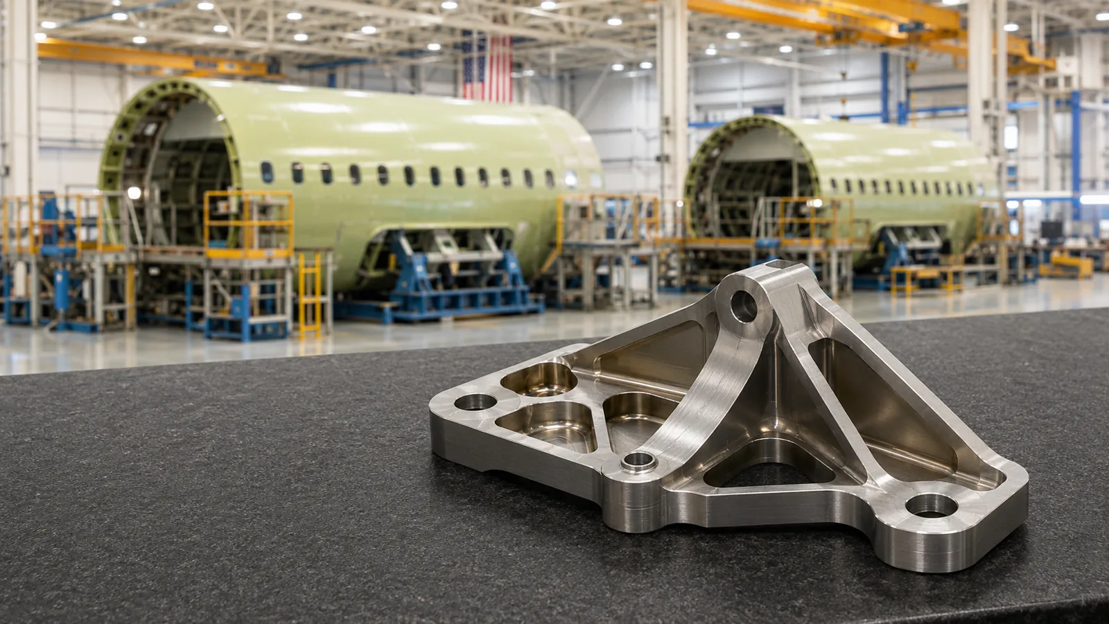
Limit tolerances are particularly crucial in high-stakes industries like aerospace and automotive, where even the smallest dimensional error can lead to significant performance issues. For example, a piston in an engine must fit perfectly within its cylinder. If the piston is too large, it won’t fit; if it’s too small, it could lead to inefficient combustion and engine failure. By defining clear upper and lower bounds, limit tolerances safeguard the integrity of the entire system.
However, applying these tolerances requires a balance. While tighter tolerances ensure better precision, they also increase manufacturing complexity and cost. It’s about finding the sweet spot—tight enough to guarantee performance but not so tight that it drives up production costs unnecessarily.
Geometric Tolerances:
While dimensional tolerances focus on size, geometric tolerances take precision a step further by controlling the shape, orientation, and position of features on a part. This is where Geometric Dimensioning and Tolerancing (GD&T) comes into play, providing a standardized language for defining these critical characteristics.
Geometric Tolerances ensure that a part’s features—like holes, surfaces, and slots—are not only the correct size but also correctly aligned and positioned relative to other features. This level of precision is crucial in complex assemblies where multiple parts must fit and function together seamlessly.
Here are the key elements of GD&T:
- Flatness: This tolerance controls how flat a surface must be, ensuring there are no bumps or dips that could affect the assembly or function of the part.
- Perpendicularity: This specifies how perfectly perpendicular one surface or feature must be to another. For example, if a hole needs to be drilled straight down into a flat surface, perpendicularity ensures that the hole is perfectly vertical.
- Concentricity: This controls the alignment of two or more cylindrical features, ensuring they share the same central axis. It’s critical in parts like gears or shafts where precise alignment is key to performance.
- True Position: This defines the exact location where a feature should be, considering all potential variations in the part’s geometry. True position is often used for holes or other critical features that must be placed precisely to function correctly within an assembly.
GD&T provides a more comprehensive way to specify and control these aspects of a part’s geometry, ensuring that parts not only fit together but also function as intended under operational conditions. By using GD&T, engineers can communicate the exact requirements for a part’s shape, orientation, and position, reducing the likelihood of errors during manufacturing and assembly.
Surface Finish Tolerances:
In CNC machining, surface finish isn’t just about appearance—it’s crucial for part performance. Surface finish tolerances dictate the roughness or smoothness of a surface, impacting everything from wear resistance to friction. For high-stress or high-friction environments, like aerospace or medical devices, getting the surface finish right is essential.
Surface finish is measured by Ra (average roughness), with lower values indicating smoother surfaces. The choice of surface finish depends on the part's function—smoother surfaces reduce friction and wear, while rougher finishes might be needed where some friction is beneficial. The machining process and material used play significant roles in achieving the desired finish.
In summary, specifying the right surface finish tolerance ensures that parts perform as needed in their specific applications, making it a critical aspect of CNC machining.
Precision vs. Cost
Achieving the right balance between precision and cost in CNC machining is crucial. While tighter tolerances improve performance, they also drive-up costs due to the need for more precise machines, better materials, and longer inspection times.
The key is to apply tight tolerances only where necessary, like in critical aerospace components, and opt for looser tolerances where slight variations won’t affect performance. For example, a tolerance of ±0.01 mm (about 0 in) might be essential for a high-precision part but could be overkill for a less critical component, where a ±0.1 mm (about 0 in) tolerance would suffice and be more cost-effective.
Ultimately, balancing precision and cost ensures that your parts meet quality standards without inflating production expenses, maintaining both product integrity and profitability.
Conclusion
Understanding and applying the correct tolerances in CNC machining is not just about following technical guidelines—it’s about ensuring that every part you produce performs reliably and fits perfectly within its assembly. By mastering the various types of tolerances, from general and limit tolerances to more complex geometric and surface finish tolerances, you can achieve the precision necessary for even the most demanding applications.
Whether you’re in aerospace, automotive, or any other industry where precision is paramount, getting tolerances right is critical to the success of your projects. By balancing the need for precision with cost considerations, you can deliver high-quality products that meet both your performance requirements and budget constraints.
- precision machining
- cnc machining
- tolerance
More from the journal.
Have a part that has to perform?
Send your 2D and 3D files. Our engineers review them for manufacturability and get back to you.